|
12.3.3. Tutorial 3 - CAD/CAM
In this tutorial, we are going to show the process of creating a drawing that we will then cut out using the unlimited milling machine. This is a long and fairly advanced tutorial. Make sure you complete the more basic ones first.
This is the part we are going to make today:

It is a good idea to print the drawing before starting the tutorial. Then you do not have to scroll back to look at it. You can find the drawing in the SimCam samples folder.
This tutorial is made in millimeters. Go to the program settings and change to millimeters if you are using inches.
Load the unlimited mill.

Remember to save the project frequently so that you do not lose any work if the power goes out or the computer crashes.
Another good thing to remember is that if you do a mistake, you can always undo your last step but pressing Ctrl - Z on the keyboard.
Let's get started!
Drawing the part
As you can see, the part is symmetrical. We can draw just one side of it and then mirror it around the center line. Let us draw the left side.
We can use the diameter 100 circle as the drawing origin for now. Later we will change the origin for the CNC output.
Start by drawing the center line.
Click on the grid settings button  and set 1 mm as grid spacing.

Click [Line] - [Drawing Line].
Move the mouse to X0 Y-177 and make your first click.
Move the mouse to X0 Y167 and make a second click.

Now we will change the properties for the line so it looks more like a center line.
Click two times on the line, the first time to activate it and the second time to show its menu.

Click [Modify] - [Properties] - [Open].
Enter these settings for the object style:

Click OK.

Now, let us draw this line:

On the other side of the drawing, we can see that the angle for the line is 12.953 degrees.

As we are on the opposite side, we need to draw the line at 180 - 12.953 = 167.047 degrees.
Click [Line] - [Drawing Line].
This time, let us enter the coordinates via the keyboard.
Click [Enter coords].
Type in X0 Y-147.5 and click OK.

Click [Enter angle].
Type in 167.047 and click OK.

Drag the mouse to the left to set its length. Move the mouse to X-250 and click.

Now let us draw this line:

Click [Line] - [Drawing Line] - [Enter coords].
Type in X-97.5 and Y42.5. Click OK.
Click [Enter angle] and type in 194.697. (90+104.697).
Move the mouse to X-250 and click.

Let us connect the two lines on the left side.
Click [Line] - [Drawing Line].
Make sure you have endpoint snap activated.

Move the mouse to one of the lines endpoint (to the left) and let it snap, then click. Repeat on the other line.

Let us now do these two lines:

Click [Line] - [Drawing Line].
Click here:

Click [Enter angle].
Type in 90 and click OK.
Click [Enter length] and type in 105. Click OK.
Click [Line] - [Drawing Line].
Click at the endpoint of the last line you made, then drag the mouse to the right to X0 and make a final click.

Great! Let us now add the four R20 corner fillets.
Click once on this line:

Click on the top handle to show its popup-menu.
Click on the Fillet button.

Enter 20 in the bottom input field and press Enter.

Repeat on the other corners.


For convenience, let us create a group of the objects we have drawn so far (not including the center line).
Hold down Control on the keyboard and click all solid lines and arcs. Keep holding down Control until they are all selected.

Right-click anywhere in the window and select [Group selected] from the menu.

Now if you hover the mouse over any of the objects you will see that it is part of a group.

From now on, these objects will be treated as one object.
Let us add the circles!
We add points as center references.
Click [Point] - [Enter coords].
Type in X-70 Y117.5 and click OK.
Repeat and type in X-212.5 Y-25.
Create a final point at X-35 Y-105.
Click [Circle/ Arc] - [Drawing Circle/ Arc] - [Center - Radius].
Let the mouse snap to the point and click.

Drag the mouse until you read R10 and click.
Hold down the SHIFT key and press Enter on the keyboard to create a whole circle.

Repeat and create a circle with radius 17.5 at the same center. This time, click on [Enter radius] and type in the radius.

Let us group the three objects we just made.
Right-click anywhere in the window then click [Select Window] in the menu.

Click above and to the left of the circles, and then drag the mouse to enclose the objects.

Click again to select the objects.

Right-click the window again and select [Group selected] from the menu.

Now we can create copies of the group.
Hold down SHIFT on the keyboard, then click and drag the group to a new location and release.

Repeat one more time so you end up with three groups.

Now we can move the two copies to new locations.
Click on one of the groups and select [Modify] - [Move] from the menu.

Click the center point as a reference point.

Click on the leftmost point.

Repeat and move the last group to the bottom point.
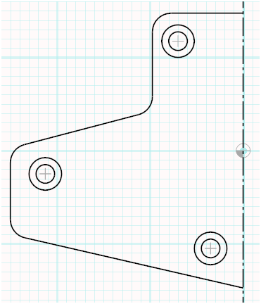
Great! Let us continue with the pocket.

We can use the offset function to help us create the pocket.
Click [Modify] - [Offset] - [Distance] and type in 20. Click OK.

Click on the line above the pocket and then somewhere under it.

Click on the line below the pocket and then somewhere above it.

Now we need to change the offset distance. Click [Distance] and type in 72.5. Click OK.

Click on the line to the left of the pocket and then somewhere to the right of it.

Change the distance to the width of the pocket. Click [Distance] and type in 70.036. Click OK. Click on the line you just made and somewhere to the right of it.
We now have four lines that can be edited to make out the sides of the pocket.

Hit Esc on the keyboard to cancel the offset function.
Click on the left line to show its handles.
Make sure you have at least Endpoint and Intersection snap activated.


Drag the top and bottom handle so the endpoints of the line intersect with the top and bottom lines.

Do the same thing with the other three lines.

Let us put in the corner radius.
Click on the top line and then on its endpoint handle followed by the fillet button.

Type in 20 at the bottom of the window.

Press Enter.
Repeat for each corner.

Good work!
Let us draw the circular slot.

We can use guide lines and circles to help us with the slot.
Click [Circle/ Arc] - [Guide Circle] - [Center - Radius].
Let the mouse snap to the zero point and click.
Click [Enter radius] and type in 70. Click OK.

The drawing shows us that the centers of the end arcs are 90 degrees apart.

Let us draw guide lines at 180 - 45 and 180 + 45 degrees.
(180 degrees because we are drawing on the right side.)
Click [Line] - [Guide Line] and then at the zero point.
Click [Enter angle] and type in 135. Click OK.
Once again click [Line] - [Guide line]. Click the zero point.
Click [Enter angle] and type in 225. Click OK.

Now we will draw the two side arcs of the slot.
Click [Circle/ Arc] - [Drawing Circle/ Arc] - [Center - Radius].
Click the zero point.
Click [Enter radius] and type in 80. Click OK.
Let the mouse snap to the upper intersection point between the guide circle and the line.

Click there and let the mouse snap to the bottom intersection.

As you can see, the arc ghost preview goes in the wrong direction. Hit space to flip it.
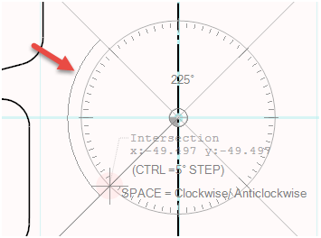
Now the arc is correct. Click at the bottom intersection.

We can use the offset function to create the other side of the slot.
Click [Modify] - [Offset].
Click [Distance] and type in 20 (the width of the slot). Click OK.
Click on the arc and then on its right side.
Hit Esc on the keyboard to end the offset function.

We will now draw the arcs at the end of the slot.
Click [Circle/ Arc] - [Drawing Circle/ Arc] - [Center - radius].
Let the mouse snap to the top intersection between the guide circle and the line and click.

Make another click at the intersection of the guide line and the outside arc.

Click one more time at the same point to tell SimCam that we want this location to be the start angle of the arc as well.
Move the mouse to the intersection on the other side. Hit space on the keyboard to flip the direction of the arc and make a final click.

Repeat this procedure at the bottom of the slot.

Let us clean up the drawing by deleting the guide circle and the guide lines.
Click on each object and select delete from its context menu.

Now we should have:

If you have not yet saved your drawing, this is a good time to do it.
We are now done with the part of the drawing we are going to mirror.
For convenience, let us make a group of everything except the center line.
Press Ctrl - A on the keyboard to select everything.
While holding down Ctrl, click on the center line to deselect it.
Right-click anywhere in the window and select [Group selected].

Click on any object in the group and then select [Modify] - [Mirror].

Hold down Shift on the keyboard (to make a copy) and click on the center line.

Almost done!
Let us draw the holes in the center.
Click [Circle/ Arc] - [Drawing Circle/ Arc] - [Center - radius].
Click the zero point.
Click [Enter radius].
Enter 40 and click OK.
Hold down Shift and press Enter.
Repeat with radius 50.
Done!

Save the drawing before we continue.
Create toolpaths
We will now create toolpaths so we get a CNC program.
For this, we need a workpiece. Let us create it!
Press F2 on the keyboard to open the inventory browser.
Click on the Mill Workpieces tab.
Click on the Add button.
Type in Workpiece Name: "CADCAM Tutorial". Type in the workpiece size according to the picture below.

Click OK.
Now we need to add the workpiece we created to the SimCam document.
Click [More] - [Workpiece].
Use the arrows to browse to the last workpiece (the one we created).

Click OK.
As you can see, we need to move the workpiece to the correct position.

Click on the workpiece and select [Modify] - [Move] from its context menu.
Type in X-255 and Y-155 at the bottom of the window.

Press Enter.

Now we will move the origin for the CNC program.
Click [More] - [CAM Settings].
Type in X-255 and Y-155 here as well.

Click OK.
Note how the origin symbol has moved.

We are all set. Let us start by cutting the pockets.
First, we have to break apart the group we did earlier.
Click on the left side of the contour and select [Modify] - [Break apart].
Do the same thing with the right side of the contour.
Click on one of the objects for the left pocket.
Select [CAM] - [Pocket] from the context menu.

Fill in the following data:

Click OK.
Click on the toolside arrows until the toolpath is inside the pocket.

Click on Done!
Repeat the process for the right side pocket.
Click on the Play button to simulate and check that everything is OK so far.

Note that you can fine-tune the way the pockets (and other operations) are cut later by going into the parameters for each operation layer.
Click on the SimCam tab to go back to SimCam.
Click on the larger center circle and select [CAM] - [Pocket].

Fill in these values:

Click the arrows so that the toolpath stays on the inside of the circle.

Click Done!
Click on the layers button if you do not have the layers panel open.
Click on the eye icon on the last layer to hide it.
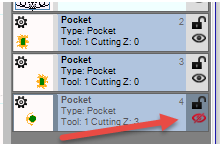
Now repeat the pocket procedure for the smaller center circle.
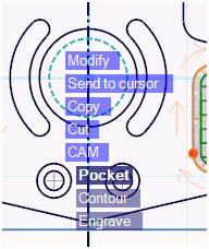
Use the following values:

Make sure you change the toolpath to go on the inside and click Done!
In the toolbar of the layers panel, click on the bulb and then select Show All.

Simulate again.

Now we will cut the two slots.
We will first manually create a contour layer (as we are not using the CAM menu for this operation).
In the toolbar of layers panel, click on the gear button. Select Contour from the menu.

Click the little gear icon at the new layer.

Click the gear icon in the tool window and fill in the following values:

Click OK.
In the Cutting Operation Parameters form, fill in these values:
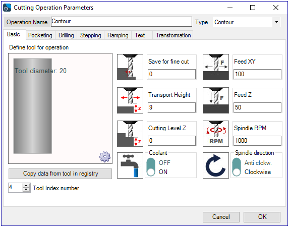
Click OK.
Now we need to add a contour to the layer so that SimCam knows what to cut.
Click [More] - [Contour] - [Track].

Let the mouse snap to the endpoint of this arc.

Click, then let it snap to the other end of the arc.

Hit Esc on the keyboard to end the tracking operation.
Make sure you change the toolside to go on the inside.

Now we are going to show you a little trick to do the slot on the right side.
In the layers panel, click on the last layer (the contour layer you just created) to make sure it becomes the selected one. It should have a yellow background.

In the layers panel toolbar, click on the duplicate button.

You will get a copy of the slot layer with the exact same objects and parameters.

On the bottom new layer, click the gear icon.
Click on the Transformation tab and enter 180 as Rotate Angle.

Click OK.
We now have both slots cut!

Let us drill the holes.
From the layers panel gear button, create a drilling layer.

Click on the drilling layers gear icon to open its parameters.
Click on the gear icon for the tool and fill out the following values:

Click OK.
In the Cutting Operation Parameters form, fill out these values.


Click OK.
Click [Point] and then click in the center of each hole.

Now we can duplicate the drilling layer and just change the parameters.
Click on the Duplicate Layer button.

Open the parameters for the new layer.
Change the data for the tool to the following:

Change the layer parameters to these:

Change the drill parameters to this:

Click OK.
Simulate.
(Note that you can press Ctrl - Q on the keyboard to do a quick simulation.)

Almost there!
Let us end by cutting the outer contour.
We are going to use the shortcut function Contour in the CAM context menu. There is a small issue we have to fix first. The center line will disturb the contour function as contours are not allowed to have intersections. We can solve this by moving it to a separate layer that we then disable.
To create a new drawing layer (guide layer), click on the plus button in the layers panel toolbar.

A new layer will show up at the bottom of the layers panel.

Now click on the center line and select [Cut] from its context menu.

The line will be deleted and copied to the clipboard.
Click [Select] - [Paste] in the SimCam menu.

The center line will reappear on the new layer (as we had this layer selected).
Click on the padlock icon to disable the layer. This means that the centerline will not interfere with the Contour operation.

Click on any object on the contour and select [CAM] - [Contour] from the menu.

Set these parameters:

Click the arrow buttons until the tool goes on the outside of the contour. This is indicated by small orange arrows pointing outwards.

Click Done!
Save the document.
Simulate.

Congratulations! The tutorial has completed.
