
|
12.2.14. Draw Contours
Contours are drawn by using lines, arc and circles, and the tracker.
Contours are the base information needed for the postprocessor to create CNC code.
Lines, arc, and circles function as roads for the tracker and as it can never go off-road when tracking, you will need to have your guides in place before starting to create contours.
Guides and contours will end up in separate layers. Each contour layer will have parameters controlling the final CNC program output.
To draw a contour:
Add a workpiece by clicking [More] – [Workpiece].
Add lines, arcs, guide lines, and guide circles to work as roads or rails for your contour.
Click [More] – [Contour] – [Track] in the SimCam menu.
Click a startpoint for the contour. The startpoint has to be a snap point.

Now, either click an object in the direction you want to go or the next snap point along the contour. On circles, do not click on snap points too far away because then the tracker can go the other way around the circle (it always wants to take the shortest way). Normally, you can use the circle's extreme points to show the tracker it's way.
When you come to an intersection, and there are two possible ways for the tracker to go, click the object you want to follow (and not the next snap point).

When you reach the contour destination, press the Esc key on your keyboard.
Note those arrows along the contour?

The long arrows along the contour shows the tool direction. They are always in the direction you let the tracker go. The small arrows, perpendicular to the contour, defines the “toolside”. They are by default on the center of the contour meaning that the tool will run directly on the contour.
Contour directions and toolsides can be changed at any time. If you click the contour (please note that you need to disable the guide layer first to avoid confusion with guide objects), a context menu will be shown allowing contour modifications.
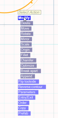
You can modify the contour in many ways like adding fillet radius and chamfers to contour corners as well as rotate, mirror, scale, move, or delete them.
To remove the Whole Contour or the Last Object for the contour, click [Modify] - [Delete] and select [Whole Contour] or [Last object]. You can also delete only a segment of a contour by selecting [Segment only]. A segment of a contour is a part that is not connected to the rest of the contour. These unconnected parts are called segments.
If you want to change the position for your contour, this can easily be done by clicking [Move] and select a point to move from and then the new position. Alternatively, you can enter the coordinates in the fields X an Y at the bottom of the window.
Contours can also be rotated. Click [Rotate] and select a center point to rotate around, then select a start angle and a new angle to rotate to. You can also enter the new angle at the A input box at the bottom of the window.
You can mirror the contour by clicking [Mirror] and select a mirror line. Please note that you need to have drawn a guide line beforehand that is going to work as your mirror.
Change the size of the contour with the [Scale] option. Scaling is done around the Origin point of the contour.

The origin point can be changed. Click [Modify] - [Origin] and move the origin point to a new position.
You can make a fillet radius at a contours corner by clicking [Modify] - [Fillet] close to a corner of the contour and then enter a value in the radius box, at the bottom of the SimCam window.
To chamfer a contour corner click [Modify] - [Chamfer] and then enter a value in the radius box at the bottom of the SimCam window. Both sides will be shortened by the value and connected by a new chamfer line.
The optimize function is convenient to use when you have imported contours from DXF files or when you have used the [Merge visible layers] function. By clicking [Modify] - [Optimize] SimCam will try to find the start of the contour and then put all objects (lines and arcs) in order creating a chain (contour) of subsequent objects.
When a contour consists of several non-connecting segments, you can use the Break apart function. Click [Modify] - [Break apart] and it will break the contour apart and create several stand-alone contours. It can be especially useful when importing contours from DXF files.
Append - You can append (extend) contours by either tracking guide lines and arcs or by selecting [Follow mouse] in the sub-menu shown.
Toolsides can be left, neutral and right. When neutral, no perpendicular arrows will be shown and the tool will go on the contour (not to the left or right).
Each time you click [Flip toolside] the toolside of the contour will cycle through: left – neutral – right.
Click [Reverse contour] to change its tool direction.
Set the parameters for the contour by clicking [Parameters].
Click [Entry/Exit] to add a smooth entry and/or exit.
It is possible to have several contours on the same layer. To change the order of the contours, just click [Order] and then [Move up] or [Move down].
Copy contours from one layer to another is easy by clicking [Copy], select another layer and paste the contour onto it by selecting [More] - [Paste] in the SimCam menu to the left.
Prefab - click this option to create a prefabricated lathe workpiece from a contour. Read more about this function here.